Saturday, February 22, 2014

B3 hatch openings cut and backing plates installed

After completing the installation of bulkheads 4 through 7, the next order of business is to install B1 - B3.   However, I wanted to install access hatches in B3, and decided I should do that before installing the bulkhead, as it's much easier to work on now.

I needed to cut out the hatches, manufacture a backing plate for the hatch to seal against, and make hatch stiffeners to reinforce the hatch itself.  I decided to make a router template to make all the cuts.

First I did some paperwork to figure out the template spacer diameters I would need.  I used a 1/8" bit to cut out the hatch, a 1/4" diameter bit to cut the groove for the gasket, and a 1/2" bit to cut the inner rim of the backing plate.


With dimensions in hand I moved to the lathe to cut out the spacers.  I used a template guide with no spacer for the first cut, so just needed to create two.  I used 1/4 aluminum.  In the photo above you can see dimples on the spacer where I hit it with a ball pein hammer to snug up the inner diameter.


I then drew out the template.  The opening size I decided on was 12" x 18", and I needed a line outside that to account for the first template guide.  I then cut out the template with a jig saw, and smoothed it with spokeshave and drum sander.


Then clamped the template to B3, took a deep breath, and cut out the hatches.


As I was cutting out the backing plates, I realized I could also cut the hatch stiffeners from the same piece of ply, using the same template, by making a big spacer (about 6" diameter).  I cut that spacer out of plywood, and it worked fine.


 After cutting out the backing plates, I checked for fit.  Looks about right.


Next I laminated the hatch stiffeners.  I am using two layers of 1/4" baltic birch plywood.  Nice wood.  I would have bought 1/2" thick if it was available.


And then laminated the backing plates.


After cleaning up the glue squeeze out, rounding over the edges, and an overall sanding, I 
installed the backing plates in the bulkhead and cleaned up the glue squeeze-out.  

I had to clampea board across the bulkhead to keep it from sagging from the weight of the clamps!


Nice to have that job done.  There will be a little followup work on these to coat with epoxy, but I can do that after the bulkhead is in the boat.

I'll be able to use this same technique for the seat-top hatches and the cockpit sole hatches.  I can use the same router bits and template spacers, I'll just need to make a new template for different sized hatches.  Should go a lot quicker next time.

Monday, February 17, 2014

First bulkheads installed

It's a milestone!  The boat is now in 3D!  No longer a collection of flat panels, I've finally got some very visible progress.  Bulkheads 4 through 7 and the seat longitudinals are now all in place, glued and filleted.

This was a bit of a nerve-wracking process.  There were a lot of moving bits and some slippery with glue.  A second pair of hands was very welcome.  Once the fillets hardened up, all the pieces are very firmly fixed together and the whole structure has stiffened up.

Working around the limber holes was tricky, and I have a little bit of further work to do here before I'm satisfied.


These fillets are not perfect, but are pretty good.  I can spend a little time removing rough spots after all is hardened up.


Here's a view down the startboard side from the bow.  The round hole is in bulkhead 4 and will take a 6" hatch.


All in all, I'm very pleased with this latest progress!


Thursday, February 13, 2014

Bushing rework, Bulkhead 7 modification

I celebrated a little too soon regarding my nicely aligned bushings in the centerboard case.  This last one to be installed had only been curing about 12 hours, so the epoxy was not fully set, and when I dry fit it in the hull and left it overnight it had a chance to sag.  I discovered it the next day when the epoxy was fully cured.

I trial fit the centerboard in the case, and it was not too badly out of alignment, probably would have been serviceable, but I decided to fix  it.


I heated up the bushing and epoxy with my Milwaukee heat gun (very handy tool).  That softened the epoxy up and I was able to push the bushing out of the hole.  When I used the high setting I charred the wood a bit, so I backed off on that.  

I drilled the recess out to 1", which gave me 1/8" around the bushing this time, vs. the 1/16" I had before, and this made it a lot easier to get the epoxy in and poke out the air bubbles with a toothpick.

I still had a couple small bubbles, and a gouged the wood a bit with a chisel.  I'll use a bit of thickened epoxy to fill in those defects.


Bulkhead 7 is the rearmost except for the transom, and it had large lightening holes in it.  The build manual suggests filling those in to form independent watertight compartments in the rear corners of the boat, and after consulting with other builders on the SCAMP forum I decided to go ahead and do that.  Access will be via a hatch on the seat top.

I cut pieces to fill the holes and applied thickened epoxy, then clamped between waxed paper and boards.


Turned out great.  This is right out of the clamps, with no cleanup.


A little scraping and a bit of sanding, and it's ready to coat with epoxy and install.


Tuesday, February 11, 2014

Pivot bushings installed

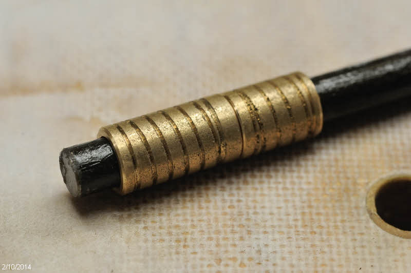
After the oversized, epoxy-filled pivot holes in the rudder and centerboard cured, I drilled them out with a forstner bit to the right size for the bronze bushings, and proceeded to prepare the bushings.  My local hardware store didn't sell bushings long enough for the full width of the parts, so I bought them in pairs.  I used one full length (1 1/8 inches) and shortened the second one to make up the length required.

I first cut the bushing to rough length with a hacksaw, then chucked it up in the metal lathe and faced of the end.  I was having fun, so decided to spend the time turning a shoulder on one part and boring a recess in the other for a nicer job.  I then turned some coarse threads on the outside to give the epoxy something to grip.


Can hardly see the joint when these go together.  Nice to have a lathe... 


Here's a shot showing the threading in progress on one of the bushings that goes in the centerboard case.


However, to save time on the rudder pivot I just used a butt joint.  


I put a piece of tape across the bottom of the holes, coated the outsides with unthickened epoxy, and inserted them in the holes.

When I installed the centerboard case bushings, I combined two steps.  Instead of drilling the holes oversized, filling them with epoxy, and then drilling them out again, I instead drilled oversize and then cast the bushings in place.

To hold them in perfect alignment, I used a spacer block that fit exactly inside the case.  I taped both sides, and drilled a 1/2" hole on the drill press.  Here's the spacer block installed in the centerboard case.


I then could put a greased 1/2" rod through the bushing and block to ensure the bushing was perpendicular.


I coated the inside of the hole with unthickened epoxy, then coated both the inside of the hole and the outside of the bushing with thickened epoxy and inserted the bushing.  Then poked around with a toothpick to try to make sure there were no air bubbles in there.  If I were doing this again, I would drill the oversized hole larger to make it easier to get the epoxy in there.  The bushing is 3/4" outside diameter, and the hole is 7/8", so just 1/16" gap.


I filled the top hole, then the next morning turned the part over and did the other side.  After the epoxy cured I removed the rod and was able to drop the pivot bolt in with no binding, so I was pleased with my success in getting these bushings aligned with each other, and perpendicular to the surface.

I liked doing this work on the flat vs. trying to install these after the centerboard case was in the boat.  Other than dealing with large parts it was fairly easy to keep holes perpendicular on the drill press, checking alignment with a small square.

Saturday, February 8, 2014

Centerboard case assembled, spacers created


I have decided to build the centerboard case outside of the boat for several reasons.  Primarily I wanted to be able to put the case on the drill press to ensure the centerboard pivot holes are perpendicular and perfectly in line.  In addition, this also lets me glue on the flat, and I can use clamps vs. drilling screw holes and having to fill those in afterward.  

I took quite a bit of time to ensure all parts were aligned, then made marks so I could replace things in the right place.  I applied unthickened epoxy to the bare wood of the case ends to make sure they were saturated, and then followed that up with thickened epoxy on both the end pieces and the case sides.

Once the glue was applied, everything was very slick, but I aligned marks and then fired in a couple pins from my pin nailer, which kept the pieces from sliding around when I applied the clamps.  That worked well.

Both these plywood pieces had a bit of a twist in them, so you can see I have the far right corner clamped down to the heavy table, and the leftmost corner pushed down with a go-bar against the ceiling to take out the twist.


Gentle clamping pressure was applied to avoid starving the joints, and the inner case corners were smoothed over with a long dowel.  In this photo you can see the end of a couple long spacer sticks lying the long way in the case to keep the sides the right distance part and make sure there is no overall bowing of the part.


I also set up the rudder and centerboard on the drill press and drilled the pivot holes out oversized.


And filled them with thickened epoxy.  After that's dry, I'll drill the holes out to accept bronze bushings.


To keep the installed centerboard in the middle of the case, I visited the local hardware store looking for some large nylon washers, but didn't find anything appropriate.  So I looked around the shop and found this chunk of plastic I picked up at a salvage yard some years ago.  I've already used a corner of this for something, can't remember what.  I traced a circle and cut it out with the bandsaw, then did my best to resaw it the thin way to yield two blanks.


As you can see below, that didn't go too well, as I had trouble with the blade wandering.  But I have plenty of thickness to work with and one flat face to start with.  I attached piece of plywood to the faceplate of the lathe, and used double stick tape to attach the plastic to that.


I faced off the plastic until it was smooth and about the right thickness (just over 1/8th inch), and trimmed the outside edge to make it round.


Then drilled the center hole.


Here's the plastic stock, rough blank, and finished part.


And here's a picture showing the overall size of the spacers on the centerboard.  They are about 3 inches across, which seems a good size to me.


Wednesday, February 5, 2014

First dry fitting, and centerboard case work


With the jig done, it was time to fasten on the bottom of the hull. Lined up perfectly centered, the hull panel is held on with four screws through plywood pads and into two cross members on the jig.


I then squared up all the routed aligning indentations with a small chisel, and squared up the corresponding tabs on the bulkheads with a file, and then did a dry-fit of the parts.  That was pretty neat - I can really get a sense of the size and shape of the hull now!


Before gluing any of that in, I need to finalize the centerboard case.  I decided to epoxy the doublers on to the panels before installation.


The next pieces I need will be the solid stock for the ends of the case, and that's still getting epoxy coats, so is delaying the process.  But that gives me time to think about where I want hatches.  

And opportunity to keep applying fairing mix and smoothing that off the rudder and centerboard. With each iteration they get closer to done...