Tuesday, July 29, 2014

Seat edges constructed and installed

I continued with the seat edge construction by using a router to round over all but the top seat edge. 


I applied several coats of epoxy on the three surfaces that form the seat-board slot, since it's easier to do that before assembly, and after that cured I applied thickened epoxy to the joints and clamped the parts together.


I didn't have any kind of bit to form the large round-over on the front of the seat edges, so I marked out the edges where I wanted to stop the cut.


And used a power plane to remove the bulk of the wood, then finished up with a spokeshave, followed by sanding with the soft pad on my random-orbit sander. 


I fit the back ends to the transom on each side, and then cut them to final length and rounded the forward ends, then coated the remaining untreated areas with epoxy.

On the starboard seat edge I routed a groove for the copper tubing to route the centerboard uphaul line and epoxied that in place.


And after it cured I trimmed off the excess tubing and made sure there were no burrs or sharp edges to wear on the line.


Finally, it was time to epoxy on the port seat edging.  I held this in place with a couple clamps and braces from the other seat front.  Short sticks support the edging at the correct height.  No screws or other fasteners needed.


And the next day glued in the other side.


I left both moldings just proud of the seat tops, so that I can plane/scrape/sand them down to the perfect height.  After painting, the transition should be invisible.  I like the feel of these edges - they are smooth and comfortable.  They add a little weight to the boat, but I think it will be worth it.

Tuesday, July 15, 2014

Seat edge design

I've been thinking about how to finish off the front of the seat edges.  The plans call for a square corner, and then a cleat 3/4" below the edge to provide a ledge for boards spanning the cockpit for a sleeping platform or rowing seat.

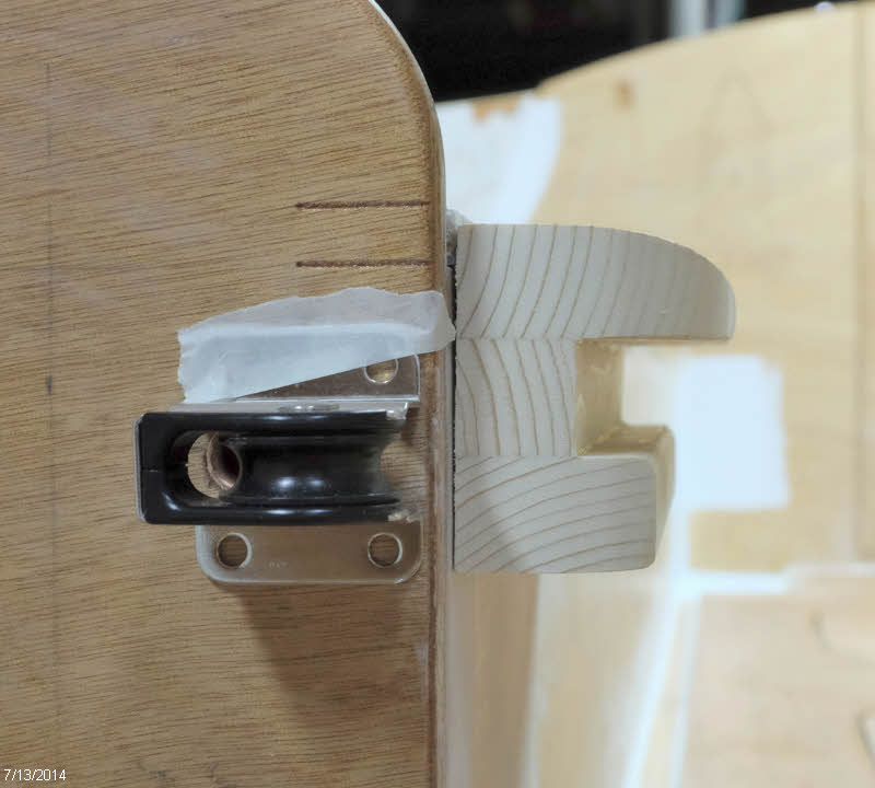
I was interested in easing the edge of the seat and gaining a little additional width.  I prototyped the shape shown in the photo below, which accomplishes that, and also provides a ledge to insert boards across the cockpit.  If I do use boards I expect to make them with a cleat underneath to fit the slot so that the top ends up even with the seat tops.


When I put my edge idea in the boat, though, I could see that I was going to have some interference with the centerboard uphaul line.  I threaded the line through the pulley and taped it down at the angle I expect it to run.


I plan to place a copper pipe in the seat edging to route the line, and I was pleased to see that it would exit the bottom of the edging in a fairly short distance.  The pencil line below shows the expected path of the copper tube.


With the plan in place, I started cutting stock for the two seat edges.  To keep the 6' 9" pieces under control during glue-up I decided to route a tongue and groove arrangement as shown below.  I sized the center piece to have a slot 13/16" high - enough to fit a standard 3/4" board with a little play.


Next I will round the edges and glue things up.


Wednesday, July 9, 2014

Seats installed

Now that the cockpit floor is installed, I next moved on to the seats.  The starboard seat gets a section cut out to provide access to the centerboard from above, which will be handy to have when installing the centerboard.  Since I don't much like square corners, I layed out a curve on the aft end.

I didn't cut this access the full length of the slot, but left it about 8 inches short.  The idea there is to have no seams at the aft end of the trunk.  I have heard that some boats with the cover cut full length could get some water splashing/seeping through the joints, leading to wet clothing, and a recommended solution for that was to have a shorter opening, so I'm trying that.  

For the long straight cut I set up a fence and used the jig saw, after first flattening the set out of the blade with hammer and anvil in order to get a narrower kerf.  


For the corner I used a coping saw, which worked out pretty well.  I should have paid a little more attention to keeping the cut vertical, but it worked out fine.


I rounded over the edges a bit with sandpaper. 


And then put the final coat of epoxy on the underside of the seats and let that cure overnight.


In the morning I spread thickened epoxy on all the cleats and edges of the seat front on set the seats in place. I took care that they fit pretty well, so didn't need any clamps - just a few 23 gauge pins to snug it down and get a little glue squeeze-out. 


I didn't glue the joint between the back of the seats and the hull panels; that joint will be secured when I apply a fillet of epoxy along the joint, which will be the next job.


I'm always glad when the big glue jobs are done!

Thursday, July 3, 2014

Sole fillets -- new recipe

No, this post is not about how to cook up the catch from your latest fishing trip -- it's about the boat again.  

After letting the epoxy cure from gluing down the cockpit sole (floor) I removed all the clamps and put a fillet of thickened epoxy around the edges.


I was able to reach over the edge of the hull from outside the boat to do the area between B3 and B4 shown below, but the area shown above was done from inside. Working on hands and knees does slow down the process.  I ended up doing this fillet in two sessions.


This was the nicest fillet I've done to date.  I did sand it a bit to remove a couple high spots, but otherwise would not have had to bother.  

This great result is due to using a new recipe for thickening the mix.  In the past I have used wood flour alone, wood flour with a little silica, and West Systems filleting blend #405.  All those options produced good strong fillets with a fairly rough surface.  The wood flour closely matches the plywood in color, and the #405 is much darker in color.

For these fillets, I made a mix of 2 parts silica, 2 parts microballoons, and 1 part West Systems #404 high density filler.  It takes quite a bit to thicken up the epoxy (about  2+ heaping plastic teaspoons-full for each pump of resin), but goes on nice and produces a smooth fillet that seems quite strong, and yet is fairly easy to sand.  


The fillet on the left is the new one, and the one on the right was West Systems #405 filleting mixture, which I then had to fair with a microballoons fairing mix because it was too rough.  I then scraped/sanded the fairing mixture smooth.

Bottom line is that the new recipe is highly recommended!

Saturday, June 28, 2014

Cockpit sole installed!

With the little hatch locating triangles installed on the bottom of the cockpit sole, it was time to give that surface a final coat of epoxy in preparation for installation.


I had trial fit the sole multiple times to ensure the process would go smoothly when all the cleats were covered with thickened epoxy.  This also allowed me to see where there were any gaps that would need clamping.

I mixed up a couple batches of thickened epoxy and applied it to the cleats, then with two helpers dropped the sole into place.  I then used some sticks and clamps to push down in a few places, and spent some time scraping off excess epoxy from the hold.  The floor hatches gave good access for this, and allowed me to confirm I had good contact.


This was a big step to get done, one that I had been dreading for some time.

Hatch hold-downs

I'm building eight plywood hatches into my boat.  One issue with hatches is how to latch them, with maybe the simplest answer being to put six or so turnbuckles around the perimeter.  I thought it would be more elegant if I could reduce that number to maybe two.  In order to attempt that, I've built in interior hold-downs for one side of the hatch.  This is an idea borrowed from another SCAMP builder.

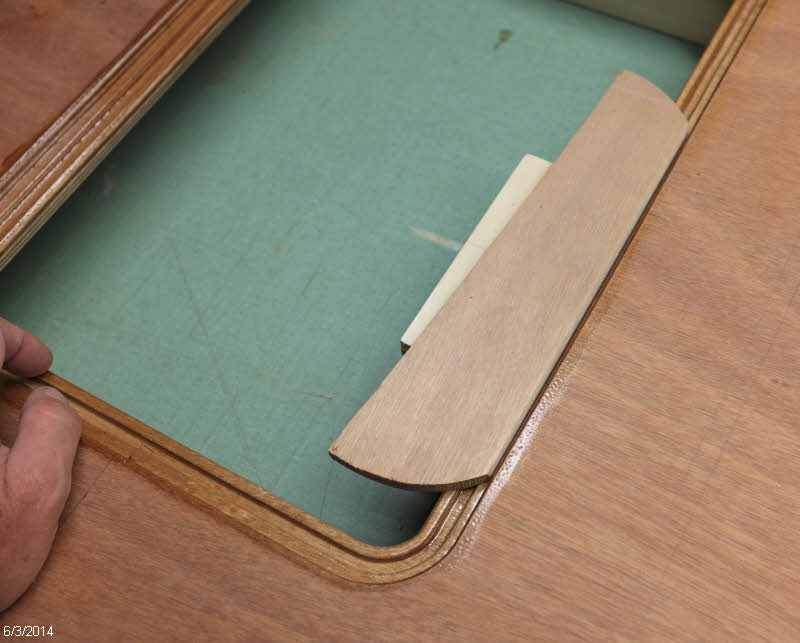
Here's the proto-type.  From the top down, there is hatch cover, hatch stiffener, and then the latch made of three layers of 9mm ply.  Notice that the latch part extends out beyond the edge of the hatch, and this is key.  It gives you room to insert the hatch into the hold, and snugs down the hatch cover on the gasket as the hatch closes.


Here's the prototype being checked for fit


I laminated a bunch of stock and cut it to length.  The two longer pieces are for the seat hatches. The V-cuts are there to locate the hatch in the center of the hole on the latch side and the two adjacent sides.  I cut them to rough dimension with the bandsaw, and then made a little router jig to make sure they are all the same.


I then made a positioning jig to locate the latches side to side and at the proper distance from the edge.


After applying thickened epoxy, I held the latch in place and shot two 23-gauge pins in from the other side to hold it in place ...


... while I removed the positioning jig and applied a couple clamps.  I really like the stainlesss pins in an application like this because they keep the parts from sliding around while putting the clamps on.


Here's the set of them all glued up. 


Next I laminated some stock from which to cut the little triangle pieces.  I inserted each hatch into it's proper hole and shimmed them in  the center.  Then applied thickened epoxy to the triangles and shot them with three pins each to locate and clamp them.  No additional clamping needed for those.  I then removed the hatch covers and cleaned up the epoxy squeeze-out. 


Getting these little triangles installed under the cockpit sole was the piece of work that has been holding me up from getting the cockpit sole glued down. See next post...

Rudder head construction

Here's the construction sequence for the rudder head.  I had a couple goals I was trying to meet.  I wanted to line the uphaul/downhaul line channels with copper pipe to reduce friction, and wanted to laminate the center section first to make it easy to clean up and finish areas that will be hard to get at later when fully assembled

I fussed around with the layout for the line channels for a while before deciding on the route shown below.  I wanted the openings to exit the front of the rudder head as near the tiller as possible, and I wanted the rear exit to be gentle, so the line would not need to take a right-angle turn there.  Using the flexible copper pipe, here's what I decided on.


Heres' the exit on the front of the rudder head


And here's the back side.  Because of the thickness of my rudder, I added one layer of 4mm ply in the center of the lamination.


 Here's the glue-up of just the center layers of the rudder head


After the epoxy cured it was time to clean up the edges and trim the tubes to length.


A small hacksaw made quick work of the protruding tubes


And a bit of sanding smooths them down nicely.  I will further round the edges before running the uphaul/downhaul lines over them.


I used epoxy/graphite mixture to match what I did on the cheek pieces


And then laminated the complete assembly.