Showing posts with label router. Show all posts

Sunday, March 15, 2015

SCAMP gets a nose job (solving a problem with a custom router jig)

To the extent I can in my small shop, I like to take a step back from time to time and admire my progress.  Generally I am well pleased, but recently something a bit out of line caught my eye.

I think this had been hiding until the contrasting paint showed up the unevenness in the trim piece I had installed at the top of the bow transom last September (see this post: <rubrails>). My intent was to have the bottom of the trim match the curve of the deck, but looks like that didn't work out:


I thought about this for a while wondering how I could most easily correct the problem.  My planes would not work on this concave surface.  A curved sanding block beveled to match the edge angle could work, but that seemed like a lot of work and not guaranteed of success.

I finally hit on the idea of making a custom router base to which I could attach a fence curved to fit the deck, and a leg to hold the bit at the correct angle.


Here's a shot where you can see how this fits against the bow of the boat.  The bit is 1/2 inch diameter, and set to the correct depth will give me a nice radius at the bottom - I won't even need to re-fillet this joint.


Here's a first pass on one side, showing the amount of material that needed to be removed.


And here's the final result before painting.  I feel good about getting this evened up.  Clicking on any of these photos should show you a larger view.


Saturday, February 7, 2015

Seat back tops laminated and installed

Before doing any more painting I next wanted to create and install the tops on the seat backs. This is the last structural part of the boat to be built, so getting this done is a great milestone.

I've been thinking over time how I wanted to handle this part.  Some builders don't have any trim installed in this area, and some builders have fairly wide tops installed, the better to sit on. Because I don't yet know whether I'll want to perch up there much, and don't know where the favored location will be if I do, I decided to just install a medium wide top, as I can always modify that later if I want to.

I decided on a top that is about 3/4" thick and 2" wide.  I laminated this up from four 1/2" strips of pine, which take the bend fairly easily.


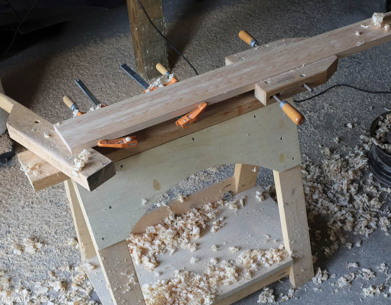
I put clear packing tape on the tops of the seats, so that I could laminate the tops in place. It was another glue-up that took most of my clamps.  I used C-clamps to clamp sticks to the seatback on the inner part of the curve, then pulled in the ends with the handscrew clamps.  I used lightweight bar clamps down to the bottom of the seat back to pull the top down to the curve, some small bar clamps with sticks to align the top of the lamination, and some small bar clamps and c-clamps to hold the laminations together.  Quite a conglomeration.


After the epoxy cured I had two tops that were curved just right to fit the seat backs.


I knocked off most of the squeeze out with a scraper, and then a quick trip through the planer had them looking nice.


The next step was to determine the edge profile.  I cut off a bit of the extra length and layed out three different radii on the edges.  My largest roundover bit is 1/2" radius, so I used that on the inner top.  I didn't want the outer edge to be completely rounded over, so used a smaller bit on the bottom edge of that.


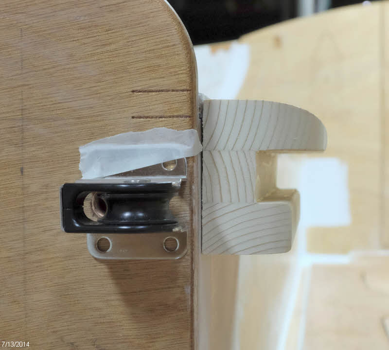
The only tricky part to fit was the return at the front of the cockpit.  This has a compound bevel where it meets the cabin side, and it's easy to get too short as you sneak up on the right fit. 


But I got this side just about perfect.  As for the one on the other side, well, that's what thickened epoxy is for...


I primed the bare wood with unthickened epoxy, and then used silica-thickened epoxy to glue down the parts. After the epoxy cured and the clamps were cleared away I was pleased with the way things were looking.


And a little sanding dresses it up even further.


When I clamped these for gluing, I tried to let them hang over to the inside just a bit, so that I could bring them back flush with spokeshave, sandpaper and scraper.  This shot is from before I did that.


After bringing the insides flush and cleaning up a bit of squeeze out on the underside I sanded them all over and then finished up with a fillet of epoxy.  Here at the cabin junction:


And all along underneath the edge.


I climbed in the boat and tried them out and found this bit of wood provides a really nice arm rest with no sharp edges, and sitting up on top for a bit to stretch my legs if wanted should be very doable, too.  All in all a nice looking and functional addition to the seat backs that finishes things off nicely.

Thursday, October 30, 2014

Shaping skegs using router and template

With the skegs rough cut and laminated, the next step was to bring them down to final dimension.  Keeping the curves fair and the right shape to fit the hull, and keeping both skegs identical was a daunting prospect.  

However, I realized that I could use the pattern I cut to trace out the parts as a router template to trim the skegs to final shape.  The first step was to screw the pattern to the rough-shaped part.


I then used a pattern bit with a bottom bearing in the router table to trim the stock to the final dimension.  As you can see, the bit is not long enough to to the entire side, and there is also a little lip on the bottom between the bearing and the bit.  This won't be a problem.


Here's a shot of the nice curve towards the stern. 


Once I went all the way around, I removed the template, and switched to a pattern bit with a top bearing. The bearing now bears against the part of the skeg that's already routed to final dimension, and brings the remainder of the edge into line.  I flipped the stock over to get both edges finished.


The masonite I used for a pattern was a little bit too short, so I now drew in the curve at the stern and cut that out with a jigsaw.


And shaped it to final dimension with my Shinto rasp. 


Looking good.  The fit to the hull is as good as you make the pattern.  In my case, I'll have to do just a bit of minor fitting before I'm satisfied.


Next I routed the finger grips in the sides of the skegs with a bit that looks like this.  This is 3/8" radius, and I cut about 1/4" deep.


The grooves look like this.  The gentle curve of the skeg was easy to run against the fence for consistent spacing.


I followed up with a 1/4" roundover bit on the edges so that my fiberglass cloth will lay over there nicely, and hand sanded the edges of the finger grooves to get rid of the sharp edge.


Next I put tape over the bottom of the holes where there were voids in the plywood, and poured in unthickened epoxy to fill those spaces.  


After that cures I will do a little fairing work to fill the slight depressions that are left, some edges that chipped out a bit, and any other irregularities.  Then I will fiberglass these parts.


Saturday, August 16, 2014

Mast, boom, and yard - making some expensive shavings

A couple posts ago I talked about installing the gunwales and carlins on the hull, and discussed the problems I was having with the epoxied scarf joints giving way under the heat of the steam. To avoid the problem when installing the carlins, I wanted to get those parts in one piece.

My thoughts turned to the four beautiful Sitka Spruce boards I have had taking up space in the garage since April or so.  These were destined to be turned into mast, boom, and yard.  But I took another look at them and realized that with judicious layout and cutting I would have enough stock to get the carlins out, too.

Since the carlins were next to be installed, I decided it was time to cut up the spruce.  These boards are so long that I had to move my tools out to the garage so that I could send the outfeed end into the great outdoors.


My first step was to snap a chalk line, set up a fence and trim with a portable circular saw to get a straight edge to bear against the fence. 


Then I made some sawdust.  Here are the eight mast staves, two pieces of the yard, two pieces for the boom, and the stock for the two carlins.  I cut off the extra length from the long carlin to scarf onto the ends of two mast staves that came out of a board that was just a bit too short. 


I sent everything through the surface planer to reduce them to dimension,  and then scarfed the two short mast staves.


I then laminated the boom and yard.


Next up was to taper the mast staves.  I decided to do this by clamping them all together and planing them down.  I layed out guide lines on the two outer staves so I could tell when I was done.


I took off the bulk of the wood with a power planer, and then finished up with hand tools, which are more precise and controllable. 


After planing the taper, I applied two coats of epoxy to what will be the inner surfaces of the hollow mast.


I set up my birdsmouth cutter in the router table to cut the edges.  I test fit the parts, and it looks like it will make a mast.  Here's the diameter of the base. 


And here's the size of the top end.


The boom and yard have tapers on each end.  I was able to saw away some of the wood on the boom, but the remainder of the machining on that and all of the shaping on the yard was with hand planes, which made an impressive pile of shavings.


Next up with these parts will be to make the plugs for the ends of the mast and glue that up, round off the corners of the boom, and plane the mast and yard to final round dimensions.

Tuesday, July 29, 2014

Seat edges constructed and installed

I continued with the seat edge construction by using a router to round over all but the top seat edge. 


I applied several coats of epoxy on the three surfaces that form the seat-board slot, since it's easier to do that before assembly, and after that cured I applied thickened epoxy to the joints and clamped the parts together.


I didn't have any kind of bit to form the large round-over on the front of the seat edges, so I marked out the edges where I wanted to stop the cut.


And used a power plane to remove the bulk of the wood, then finished up with a spokeshave, followed by sanding with the soft pad on my random-orbit sander. 


I fit the back ends to the transom on each side, and then cut them to final length and rounded the forward ends, then coated the remaining untreated areas with epoxy.

On the starboard seat edge I routed a groove for the copper tubing to route the centerboard uphaul line and epoxied that in place.


And after it cured I trimmed off the excess tubing and made sure there were no burrs or sharp edges to wear on the line.


Finally, it was time to epoxy on the port seat edging.  I held this in place with a couple clamps and braces from the other seat front.  Short sticks support the edging at the correct height.  No screws or other fasteners needed.


And the next day glued in the other side.


I left both moldings just proud of the seat tops, so that I can plane/scrape/sand them down to the perfect height.  After painting, the transition should be invisible.  I like the feel of these edges - they are smooth and comfortable.  They add a little weight to the boat, but I think it will be worth it.

Tuesday, July 15, 2014

Seat edge design

I've been thinking about how to finish off the front of the seat edges.  The plans call for a square corner, and then a cleat 3/4" below the edge to provide a ledge for boards spanning the cockpit for a sleeping platform or rowing seat.

I was interested in easing the edge of the seat and gaining a little additional width.  I prototyped the shape shown in the photo below, which accomplishes that, and also provides a ledge to insert boards across the cockpit.  If I do use boards I expect to make them with a cleat underneath to fit the slot so that the top ends up even with the seat tops.


When I put my edge idea in the boat, though, I could see that I was going to have some interference with the centerboard uphaul line.  I threaded the line through the pulley and taped it down at the angle I expect it to run.


I plan to place a copper pipe in the seat edging to route the line, and I was pleased to see that it would exit the bottom of the edging in a fairly short distance.  The pencil line below shows the expected path of the copper tube.


With the plan in place, I started cutting stock for the two seat edges.  To keep the 6' 9" pieces under control during glue-up I decided to route a tongue and groove arrangement as shown below.  I sized the center piece to have a slot 13/16" high - enough to fit a standard 3/4" board with a little play.


Next I will round the edges and glue things up.